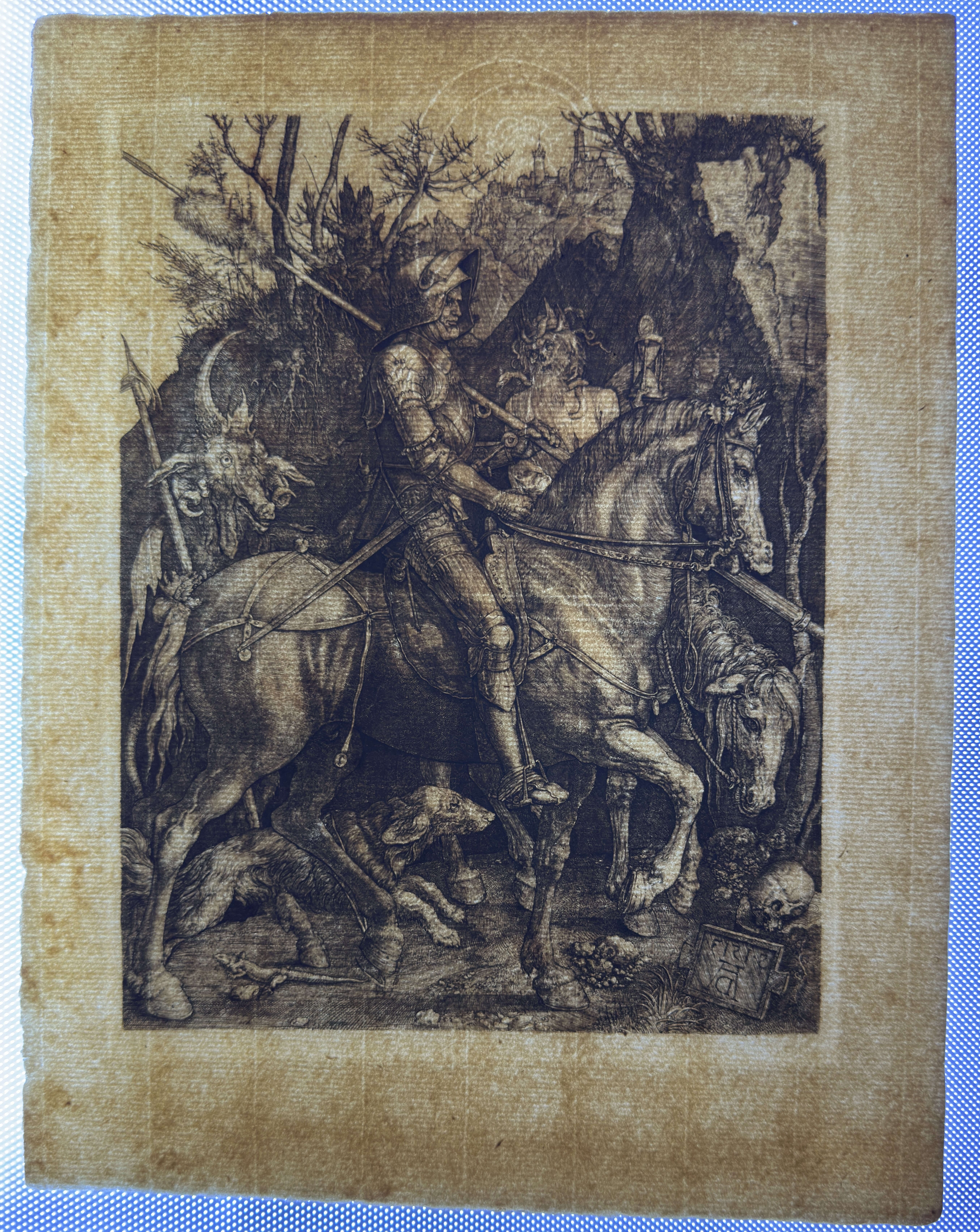
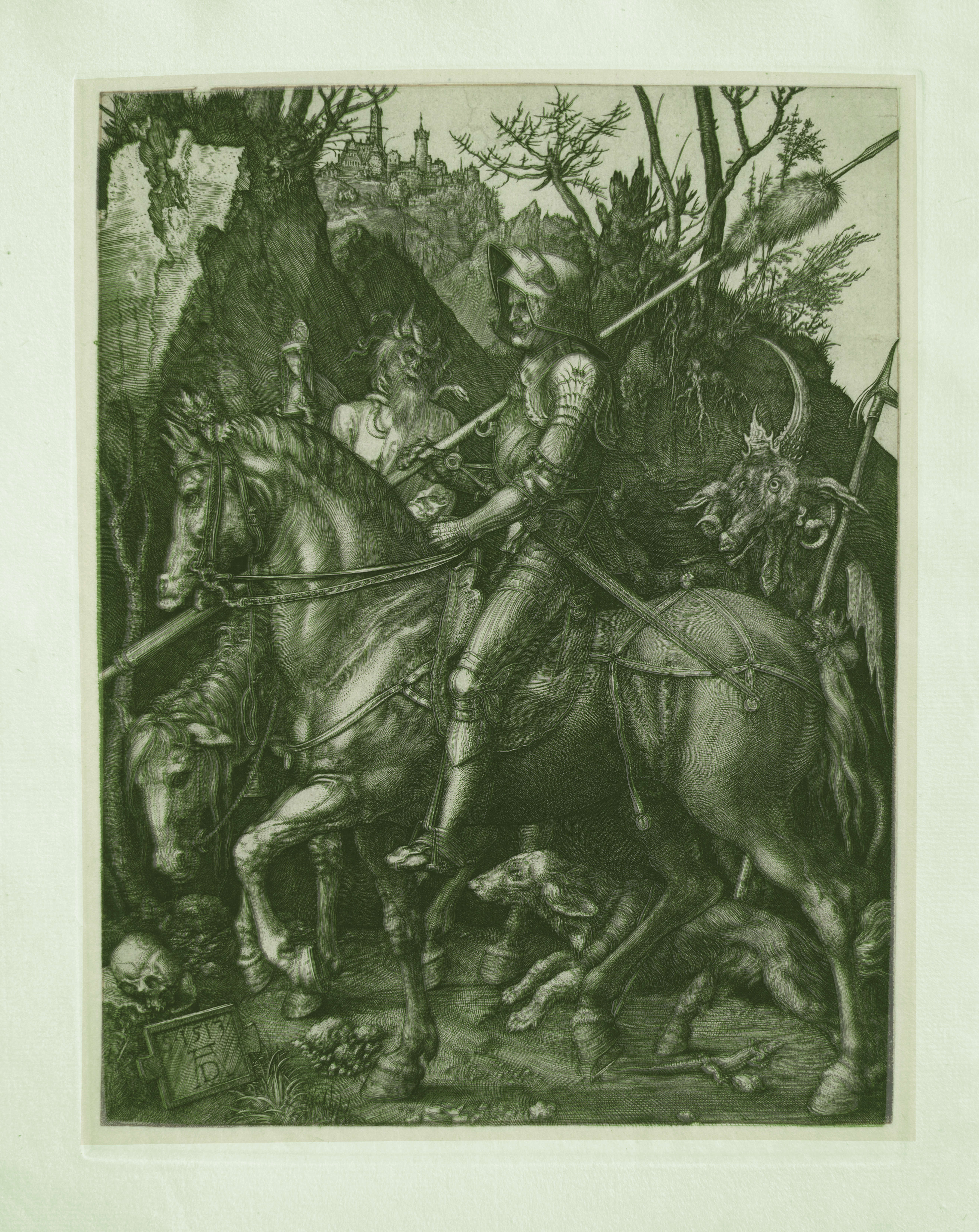
Knight, Death and the Devil — Albrecht Dürer
Technical documentation of the print through direct material observation, including paper structure (laid pattern and chain lines), ink–fiber interaction, plate mark under raking light, line morphology under macro/microscopy, and tonal mechanism analysis (dense hatching, selective burr). Comparative overlay.
TECHNICAL DATA
- File ID
- AC-AD-246-REV-2026
- Artist
- Albrecht Dürer (c. 1471–1528)
- Title
- Knight, Death and the Devil
- Date of Execution
- c. 1513
- Technique / Materiality
- Engraving (burin).
- Dimensions
- Height 246 mm × Width 188 mm
- Sheet Dimensions
- Height 320 mm × Width 245 mm
- Sheet Weight
- 10 grams
- Collection
- The Álvarez Collection (Miami)
- Provenance
- Private family collection, preserved over generations
Research Objective
Technical documentation of the print through direct material observation, including paper structure (laid pattern and chain lines), ink–fiber interaction, plate mark under raking light, line morphology under macro/microscopy, and tonal mechanism analysis (dense hatching, selective burr). Comparative overlay.


PAPER ANALYSIS
Support Structure, Chain Lines, Watermark and Printing Response
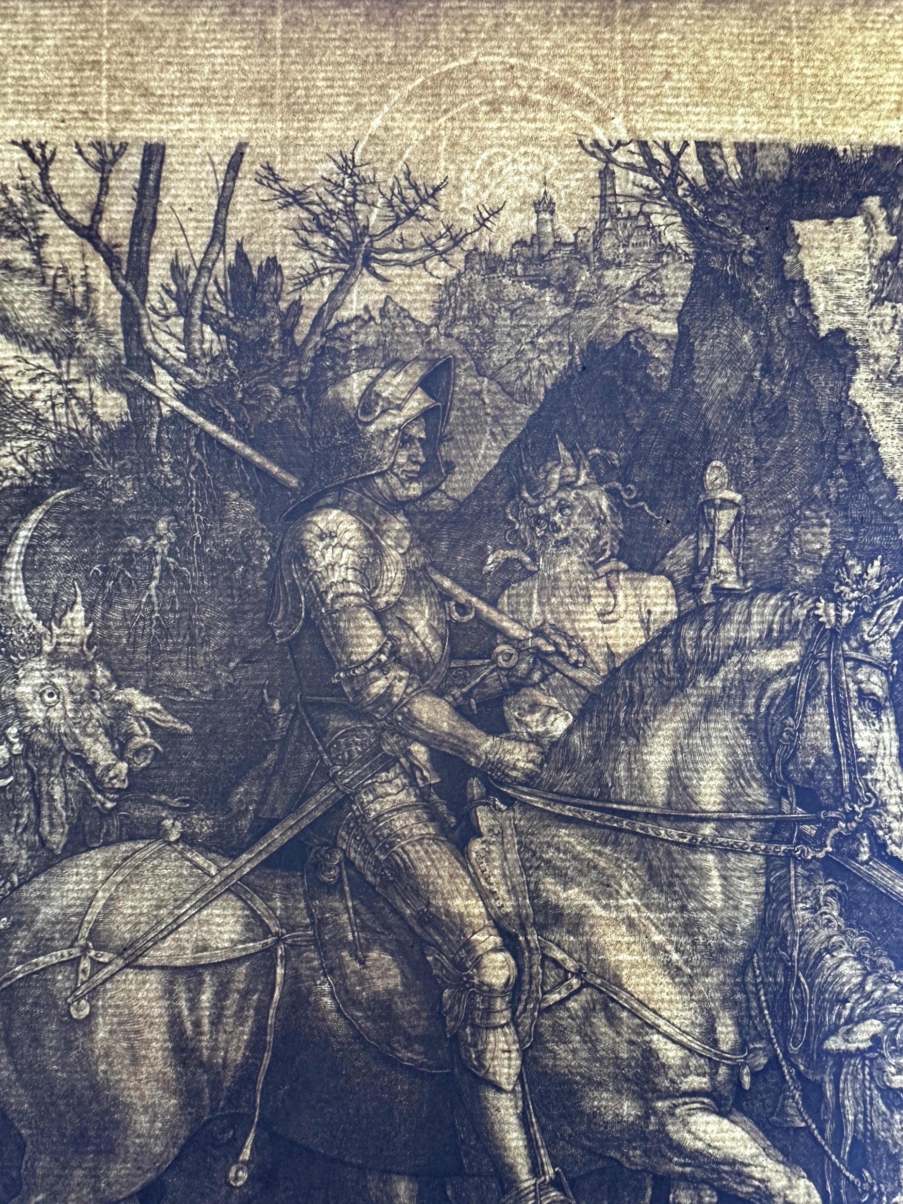
The print is executed on a laid paper produced using a hand mould, characterized by a regular system of fine laid lines intersected by a secondary system of more widely spaced chain lines. Under transmitted and raking light, the structural formation of the sheet is clearly visible, confirming its handmade origin.
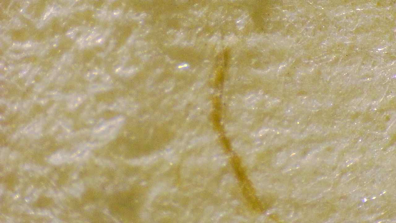
The support presents a cohesive and dense fibrous network consistent with rag-based papermaking. Microscopic observation reveals natural irregularities in fiber distribution, including occasional inclusions and variations in fiber orientation typical of historical handmade paper. The fiber network shows stable structural integrity across the sheet and responds coherently to printing pressure.
Chain Line System
Measurement of the chain line spacing reveals a recurring pattern ranging between approximately 28 mm and 29 mm, recorded across multiple observation points on the sheet. This spacing falls within the range commonly associated with high-quality laid papers historically used for intaglio printing.
The regularity of the chain line intervals indicates a stable mould construction and consistent papermaking process. The spacing pattern remains coherent across the sheet, supporting the conclusion that the paper was produced using a traditional laid mould rather than later industrial paper supports.
Watermark Structure
The sheet contains a clearly legible watermark representing a Fortuna-type motif, preserved with strong structural clarity. The watermark is formed by the impression of wire elements integrated into the papermaking mould, and its lines remain continuous and consistent in thickness, curvature, and structural articulation throughout the design.
The watermark is materially and structurally coherent with the surrounding paper formation, showing no evidence of later insertion, artificial modification, or secondary manipulation. Its integration within the laid and chain line system confirms its formation as an inherent component of the papermaking process rather than a later addition.
Fortuna-type watermark motifs are documented within established typological families recorded in classical watermark catalogues such as Briquet, including related variants catalogued under numbers 11909–11911, and are further represented in modern watermark databases including the Bernstein Memory of Paper project. These references demonstrate the recurrence of Fortuna-type designs across multiple geographic papermaking centres and chronological contexts within early modern European paper production.
Because such watermark motifs are known to circulate across extended production periods and between papermaking workshops, the watermark is evaluated within a broader morphological and structural tradition rather than as an isolated chronological indicator. Its significance is therefore considered in conjunction with the overall material characteristics of the sheet, including fibred structure, mould construction, chain line system, and printing response, all of which demonstrate coherent compatibility with handmade laid paper supports historically used for intaglio printing.
Paper Response to Printing Pressure and Plate mark Formation
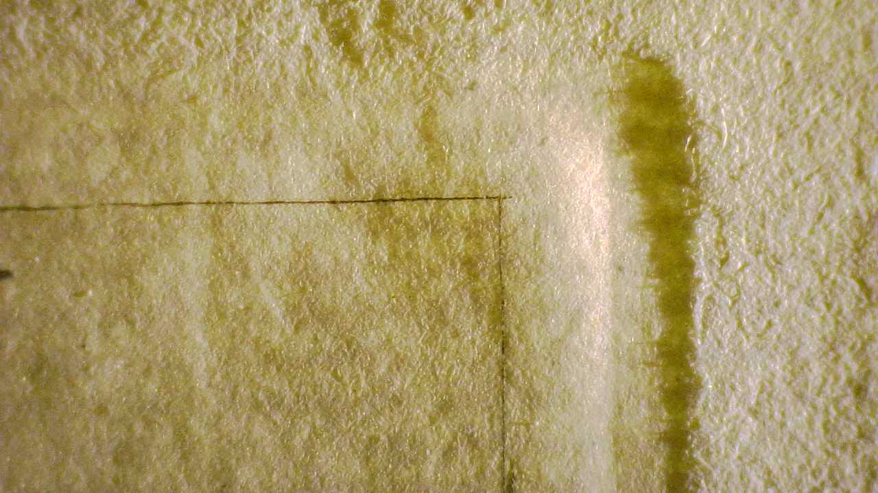
The plate mark is clearly defined and structurally integrated into the sheet, reflecting the mechanical interaction between the paper, the engraved plate and the printing press. Microscopic observation shows visible compression of the fiber network within the printed area, where the sheet exhibits increased fiber density and reduced surface irregularity.
Outside the plate mark, the fiber structure maintains its natural expansion and textural openness, allowing direct comparison between compressed and non-compressed paper zones. This transition demonstrates the physical response of the support to the pressure of the intaglio printing process.
The engraved lines interact directly with the compressed fiber network, confirming the mechanical relationship between incisions, ink transfer and paper deformation during printing.
Fiber Structure and Surface Characteristics
Microscopic examination reveals a network of interlaced rag fibers with natural variability in thickness, direction and density. Occasional isolated fibers and minor inclusions are visible within the sheet and remain consistent with handmade rag paper supports. No uniform coatings, artificial surface films or homogeneous layers associated with industrial or photomechanical paper treatments are observed. The surface structure remains organically irregular and materially coherent with traditional handmade paper formation.
Ink Interaction with the Paper Support
Observation at high magnification demonstrates that the printing ink is primarily retained within the engraved grooves and interacts directly with the compressed fiber network surrounding the incisions. Ink distribution varies naturally along the course of individual strokes, reflecting differences in pressure, engraving depth and wiping technique during printing. This interaction confirms the physical transfer of ink through the intaglio process and supports the structural integration between engraving, ink and support.
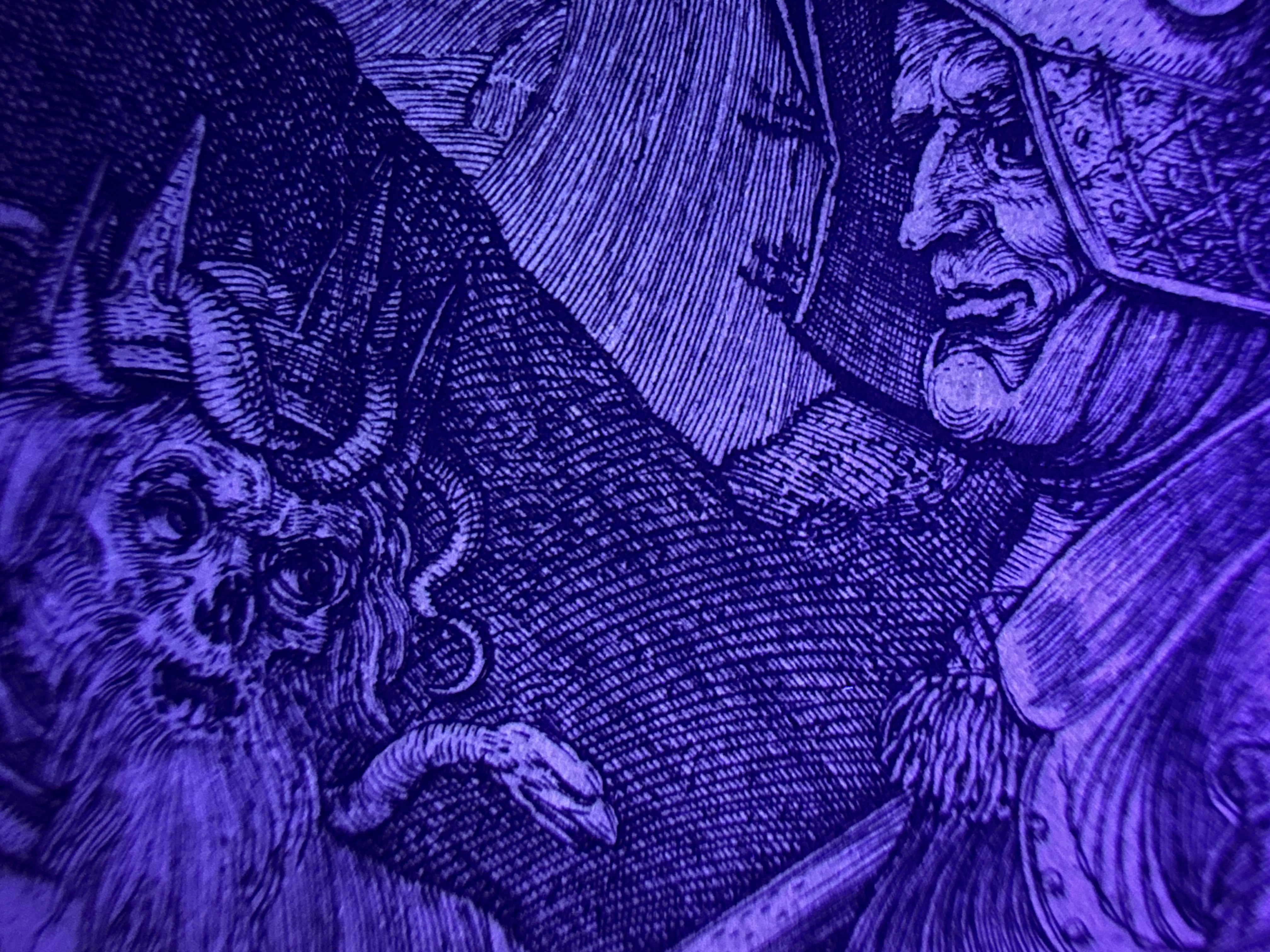
Ultraviolet Examination (365 nm)
Examination under ultraviolet illumination (365 nm) was performed to evaluate the fluorescence behavior of the paper support, the ink, and the relationship between printed and unprinted areas. Under UV-A illumination, the paper exhibits a generally soft and homogeneous fluorescence, consistent with natural ageing of historical rag paper fibers. No areas of strong localized fluorescence were observed, and no evidence of modern optical brighteners, synthetic coatings, or restoration materials is visually detected.
The printed image remains comparatively darker under UV illumination, indicating the absorptive behaviour of the printing ink and its integration within the intaglio grooves. The fluorescence pattern remains stable across printed and non-printed zones, suggesting structural coherence between ink deposition and the paper matrix. The plate mark remains clearly visible under ultraviolet illumination, showing differential compression of the fibers inside and outside the plate impression, consistent with mechanical pressure generated during the intaglio printing process.
Additional transmitted ultraviolet observations at higher magnification reveal internal variations in fiber density and distribution. The fluorescence response shows irregular clustering and stratified fiber groupings characteristic of hand-formed rag paper. These variations correspond to differences in fiber orientation, thickness, and bonding density generated during manual sheet formation. Linear fluorescence modulations are visible in repeating intervals, corresponding to the structural influence of the papermaking mould and its wire support system. These patterns reflect differential fiber accumulation rather than the direct visualization of mould wires, and they remain consistent with the expected formation structure of laid handmade paper. Localized non-fluorescent linear zones correspond to ink-filled intaglio grooves, where the printing ink absorbs ultraviolet radiation and appears optically dense. The continuity of these darker zones along engraved lines supports deep ink penetration into the fiber network, consistent with traditional intaglio printing behaviour.
Overall, the ultraviolet examination confirms the material consistency between paper formation, ink behaviour, and printing structure, and reveals no visually detectable interventions, modern additives, or surface alterations under 365 nm UV illumination.
MACROGRAPHIC ANALYSIS
The eight macro images presented in this section do not function as isolated examples, but rather as a progressive exploration of the work's complete technical system. Each detail has been selected to demonstrate how the image is constructed solely from the physical behavior of the engraved stroke, regardless of the subject matter, scale, or distance within the composition.
The macro analysis reveals that the print is governed by a unique and coherent logic of the burin, applied consistently from the main elements to the most peripheral ones. No technical breaks, procedural changes, or compensatory solutions are observed between different areas; on the contrary, the same structural language adapts to metallic surfaces, organic forms, distant architecture, and open tonal fields.
The images allow us to follow the continuous control of the gesture: the way in which the strokes begin, develop, and end responds to conscious decisions regarding pressure, direction, and rhythm. This control does not depend on the density of the grid or cumulative effects, but rather on the individual precision of each line, even when these operate at extreme registers—from heavy, deep lines to ultra-fine strokes almost suspended above the paper.
Likewise, the macro analysis reveals that volume, depth, and spatial separation are constructed without resorting to closed contours or fills, but rather through the modulation of the stroke in direct relation to the support. The paper remains active at all times, visible between lines and participating in the tonal reading, which reinforces the material understanding of the image as the result of excavated grooves rather than covered surfaces.
Taken together, these eight images demonstrate that the work is not organized by local effects or partial solutions, but by a comprehensive technical system, sustained from beginning to end. Macrophotography thus allows us to read the print not as a sum of motifs, but as a continuous structure of physical decisions, where each line—regardless of its narrative or visual function—responds to the same degree of control and technical coherence.
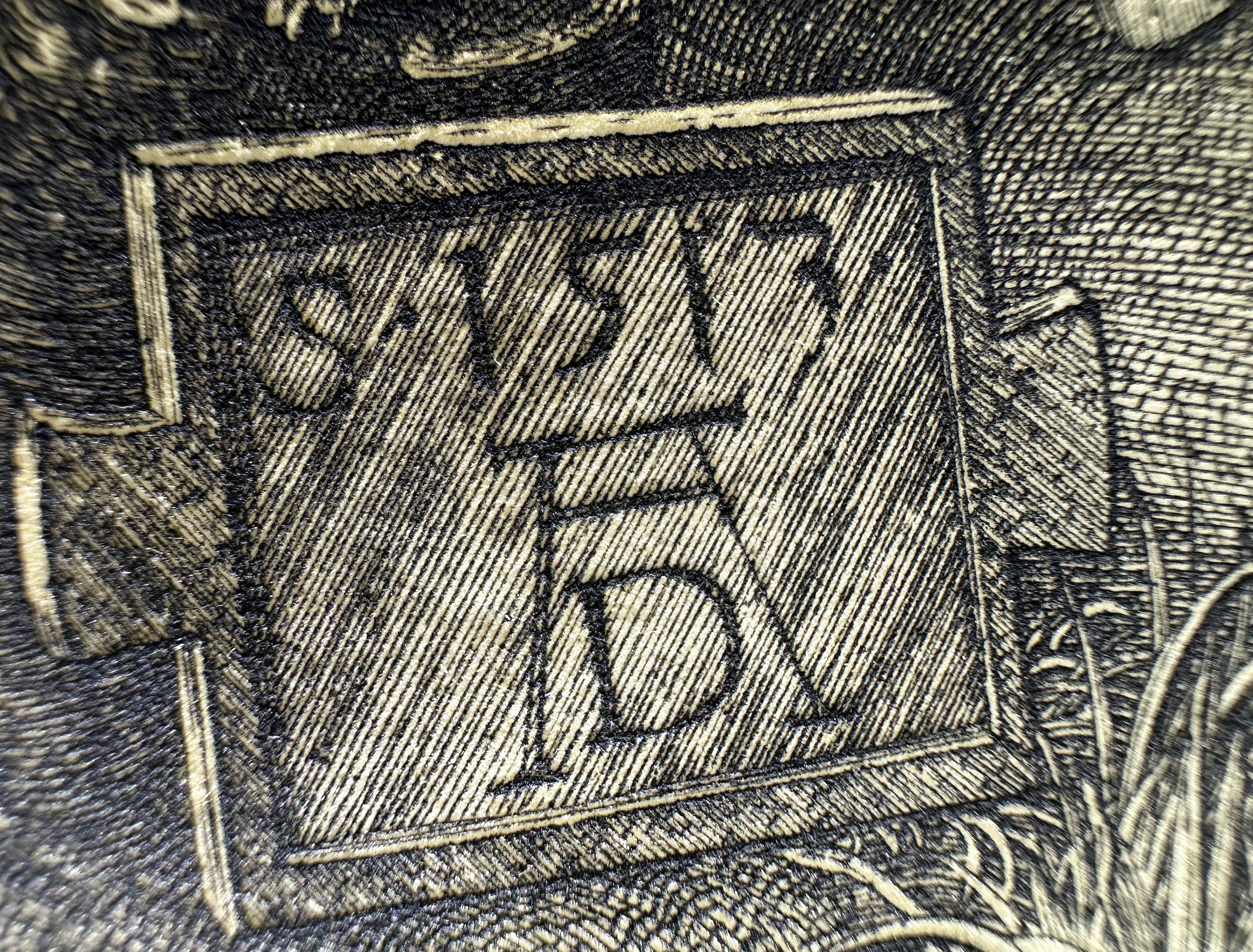
Macro detail of the AD monogram and the date 1513, showing the burin strokes with variations in pressure, defined edges, and ink held in the grooves. The surrounding hatched field reveals continuous and hierarchical hatching, structurally integrated with the outline of the letters.

Macro detail of the knight's face. The modeling is constructed with short and medium-length curved burin strokes, with variations in pressure and density. In the heavier lines, defined double edges and ink accumulation on the sides of the grooves are visible, with lighter central areas in some strokes, consistent with the V-shaped cross-section. Tonal transitions are achieved through the direction, separation, and overlapping of the hatching.

Macro detail of the breastplate plates, where volume is constructed using long, continuous burin lines, with perceptible changes in pressure along a single stroke. The lines have defined double edges and variations in ink load at the flanks, with lighter central areas in some sections, revealing the V-shaped groove. The modeling is achieved through the density, direction, and overlapping of the hatching, adapted to the edges and curves of the metal being represented.

Macro detail of the shoulder guard, where the change of plane is articulated by burin lines of varying thickness and orientation. The edges are defined by continuous strokes with sharp edges, while the volume modeling is achieved through curved and overlapping hatching. Pressure variations are observed within the same stroke and differential accumulation of ink on the flanks of the groove, visible in the areas of greater density.

Macro detail of a radial hatching field composed of burin lines that begin with a fine attack, gradually increase in depth, and end with attenuated or raised exits, visible in the gradual decrease in ink load toward the stroke's end. The lines exhibit variations in length and pressure, with open, uncut ends, allowing for continuous tonal transitions through overlapping and controlled spacing.

Macro detail of the horse's hind hooves. The volume is articulated by long burin lines that begin with a fine attack, develop progressive depth, and end with raised exits, visible in the gradual loss of ink load at the ends. Variations in length, pressure, and spacing between strokes create continuous tonal transitions, leaving the paper visible between lines and defining the curvature without resorting to closed contours.

Macro detail of the face of Death, constructed using short and medium-stroke burin lines, with thin beginnings, progressive development, and raised ends, visible in the gradual fading of the ink at the tips. The modeling of the form is achieved through the changing direction of the stroke, controlled overlapping, and variations in density, without closed contours. In the denser areas, defined edges of the groove and differential ink accumulation are visible, while the paper remains visible between lines in the tonal transitions.

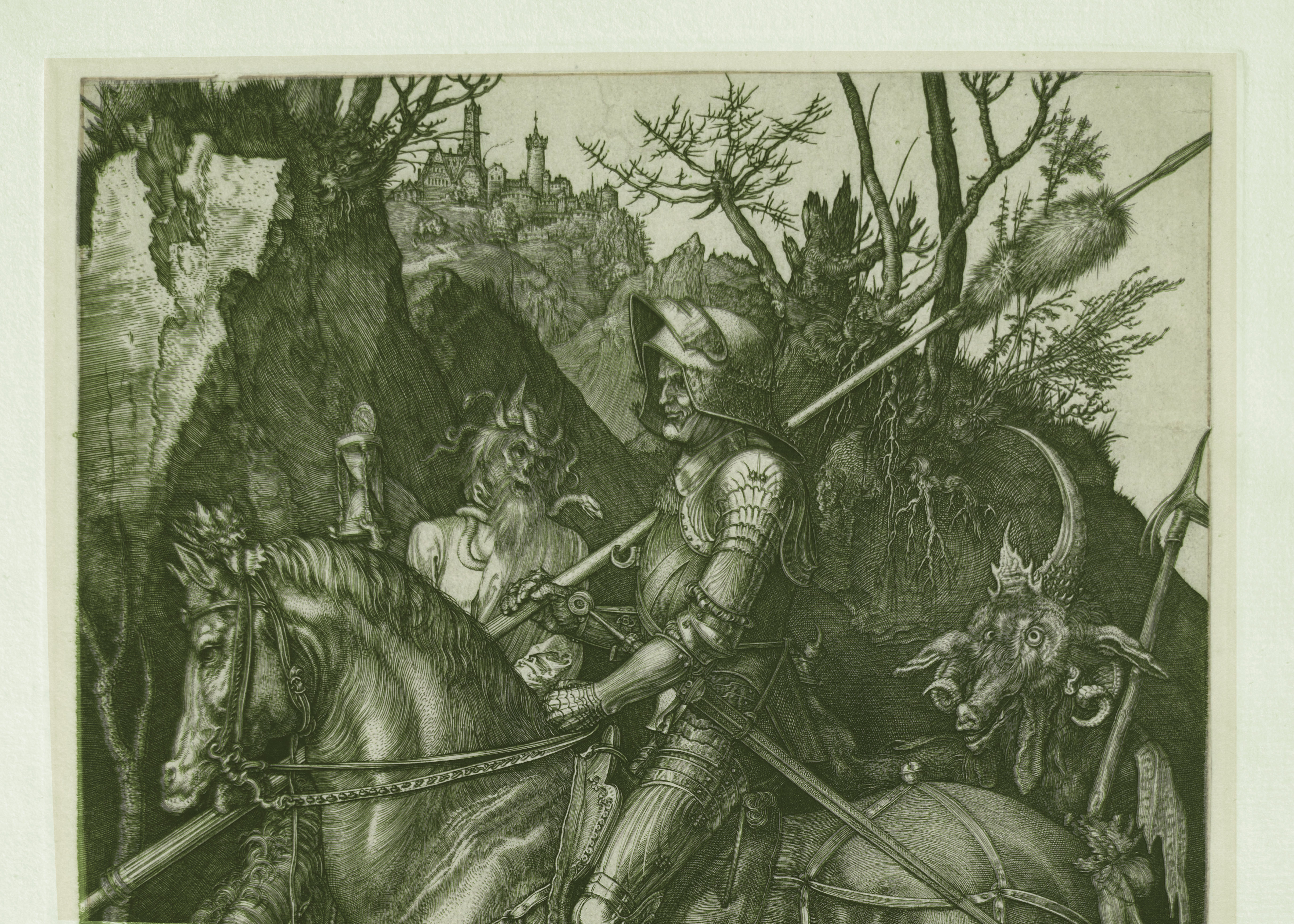
Macro detail of the castle and distant buildings, executed with extremely fine burin lines, well separated from the main field of the work. The strokes exhibit minimal attacks, long runs, and barely perceptible terminations, with very restrained pressure and wide spacing between lines. The architectural definition is achieved through the economy of the stroke and its direction, maintaining sharpness and continuity despite the extreme reduction in scale and the absence of an overarching grid.
MICROSCOPIC ANALYSIS
The microscopic section shifts the observation to the physical level of the groove and the contact between ink and support, allowing for direct examination of the material consequences of the engraving and printing process. Unlike macrographic analysis, which describes the visible organization of the line on the surface, microscopy focuses on the internal structure of the cut and the three-dimensional interaction between metal, ink, and paper fibers.
At this magnification level, the line ceases to be perceived as a graphic element and appears as an excavated three-dimensional structure, in which the groove walls, the bottom of the cut, and differentially distributed ink deposits can be distinguished. Microscopy allows us to observe how the ink concentrates on the edges of the groove, how its concentration varies within a single stroke, and how the paper fibers exhibit compression, displacement, and local adaptation under the pressure of printing.
Microscopic analysis does not address the composition or visual organization of the image, but rather documents the material response of the support and the ink to the printing technique. In this way, microscopy provides an independent and complementary interpretation, connecting the physical structure of the groove and the paper with the visible result of the print, and completing the technical study from a strictly material perspective.
Methodological Note: The microscopic images are used exclusively for descriptive and structural purposes. No interpretive filters or digital reconstructions are applied; the interpretation is based on direct observation of the groove, the ink, and the support.
The concluding microscopic images demonstrate the continuity of the engraving language across the composition, revealing the consistent relationship between incision, ink retention, and fiber deformation in both highly modeled passages and structurally transitional areas of the sheet.
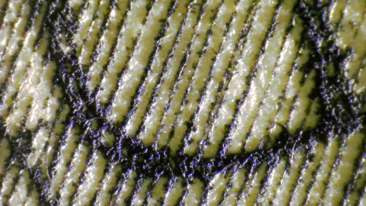
Microscopic image of a section of the monogram AD, where only partial segments of the lines corresponding to the letter D are preserved due to the high magnification. The observation allows us to distinguish the three-dimensional section of the groove, with ink accumulation on the flanks of the cut and variations in ink load along the stroke. The paper fibers show compression and lateral displacement around the lines, demonstrating the adaptation of the substrate to the printing process and the incised nature of the stroke, although the complete shape of the letter is not visible at this scale.

Microscopic image of a section where multiple incised lines intersect and overlap in different directions. Variations in ink accumulation on the flanks of the grooves are observed, as well as changes in the continuity of the ink deposit in the areas of intersection. The paper fibers show displacements and slight elevations around the cuts, demonstrating the mechanical response of the paper to the accumulated pressure of successive strokes.

Microscopic image of vertical lines corresponding to an architectural element, where the grooves appear individualized and clearly defined. Variations in the continuity of the ink deposit are observed along the strokes, as well as small accumulations at the edges of the cut. The paper fibers show localized compression and slight elevation around the grooves, demonstrating the mechanical response of the paper and the sequential execution of the stroke.

Microscopic image of extremely fine lines belonging to distant elements of the composition. The grooves appear shallow and with very contained ink deposits, maintaining stroke continuity despite the minimal pressure applied. The fibrous network of the paper is clearly visible between lines, with localized compression around the cuts and subtle variations in the distribution of ink along the stroke path.
Microscopic observation reveals the three-dimensional structure of the engraved grooves, the distribution of ink within the lines, and the physical response of the paper fibers under printing pressure. It also allows for the identification of the structural transition between the area compressed by the plate mark and the original texture of the paper, as well as natural paper irregularities and localized ink deposits associated with historical manual processes.
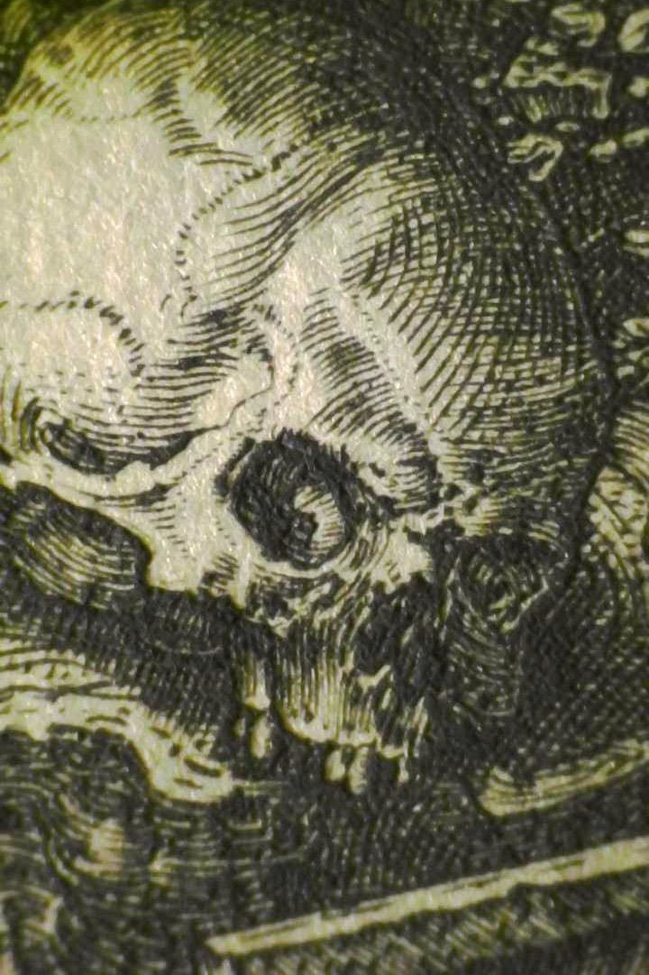
Microscopic detail of the skull showing the tonal construction through dense systems of parallel and intersecting lines. The variation in depth, spacing, and orientation of the strokes generates precise volumetric gradations, allowing observation of the direct relationship between groove excavation, ink retention, and compression of the paper fibers. The anatomical modeling is constructed exclusively through the control of the burin, demonstrating the integration between graphic technique and the material structure of the print.
DIGITAL OVERLAY AND COMPARISON WITH INSTITUTIONAL REFERENCE
Digital overlay analysis was conducted as a comparative tool to evaluate the structural correspondence between the present impression and an institutional reference impression documented in a museum collection. The purpose of this analysis is not to establish identical printing conditions, chronology, or edition sequence, but to assess whether both impressions are materially compatible with the same engraved matrix or with a coherent physical lineage derived from that matrix.
The overlays were executed using high-resolution digital images, aligned manually through stable structural anchors inherent to the engraving itself. These anchors include fixed compositional elements such as architectural contours, primary figure outlines, and internally consistent line junctions. No geometric distortion, rescaling, or corrective transformation was applied beyond uniform alignment.
Overlay A — Full-Plate Structural Alignment (1:1)
A full-plate overlay was performed to evaluate the global structural correspondence of the composition. This comparison demonstrates consistent proportional relationships across the entire engraved field, including figure placement, architectural elements, and landscape contours. The alignment supports the conclusion that both impressions originate from an identical engraved design structure.
Overlay B — Comparative Structural Overlay (Upper Plate Half)
A partial overlay focused on the upper half of the plate was carried out to reduce cumulative alignment noise and to test structural coherence within a confined zone. This regional comparison confirms the continuity of engraved forms, spatial relationships, and line trajectories at a sub-plate level, reinforcing the compatibility observed in the full-plate overlay.
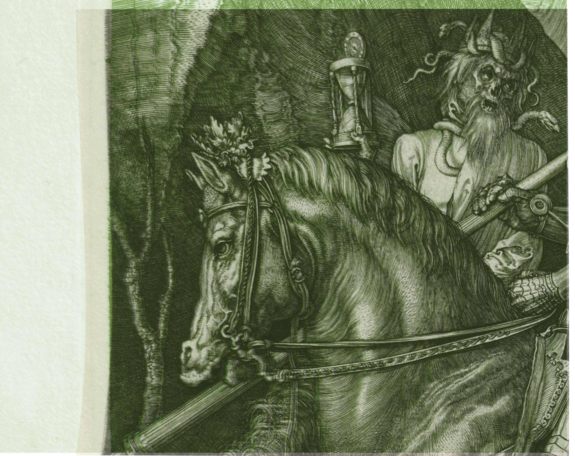
Overlay C — Localized Morphological Overlay (Horse Head and Death Figure)
A localized overlay was executed concentrating on the horse’s head and the adjacent figure of Death. This zone was selected due to its high density of complex organic line work, curved hatching, and expressive burin strokes. Within this area, the overlay reveals close correspondence in line curvature, spacing, directional rhythm, and the interaction between primary and secondary engraved lines.
This localized comparison does not assert identical impressions or identical printing moments. Rather, it demonstrates that the engraver’s original linear language—its structural logic and internal coherence—is preserved across both impressions, consistent with production from the same engraved matrix or from impressions deriving directly from it.
Methodological Considerations
Digital overlay analysis is employed here as a structural and morphological comparison tool only. It is not used to infer exact chronology, print order, or edition size. Variations in ink density, pressure, paper response, and surface condition are expected between impressions printed at different moments, even when pulled from the same plate.
Accordingly, the overlay results are interpreted in conjunction with independent technical evidence, including macrographic and microscopic line analysis, paper structure, watermark integration, plate mark characteristics, and ultraviolet examination. The convergence of these independent lines of evidence strengthens the interpretation of material coherence between the impressions.
Conclusion
The digital overlay analysis demonstrates a high degree of structural and morphological compatibility between the present impression and the institutional reference. When evaluated within the broader technical context, the overlays support the conclusion that the impressions belong to the same physical lineage of an engraved matrix and are inconsistent with photomechanical reproduction processes. The overlay evidence is therefore considered confirmatory rather than determinative, contributing to a multi-layered technical assessment grounded in material observation.
Provenance and History
The print was transmitted from generation to generation, remaining within the same family. Its state of preservation suggests minimal historical handling: it was stored for decades in a protected environment, away from direct light and damaging humidity fluctuations. It is likely that the print has been handled far less during the past one hundred years than during the recent technical examination conducted under microscopy, raking light, and transmitted-light watermark analysis.
This continuity of private custody—without recorded sales, auction appearances, or dealer interventions—helps explain the exceptional condition of the sheet and the survival of fragile physical features often lost in circulating impressions, including residual micro-relief, intact margins, and a fully preserved plate impression.
Provenance therefore supports attribution not only through lineage, but through material coherence: every aspect of the sheet’s condition aligns with an impression that has remained intact and undisturbed over time.
Access and Research Collaboration
The Álvarez Collection provides researchers, institutions, and specialists with access to the comprehensive technical dossier of the engraving. This archive includes high-resolution microphotography, original 3D metrology datasets, and incision morphology profiles processed using MATLAB® computational vision algorithms.
All topographical metrics, relief-density mapping, and frequency spectrum analyses are conducted using MATLAB® to ensure numerical consistency and reproducibility. By transitioning from subjective visual assessment to automated data extraction, we establish an empirical, physical framework that complements traditional art-historical evaluation and curatorial review..
The observations and metrics presented in this dossier are derived from the direct physical examination of the print and calibrated against institutional reference standards. Given the technical nature of these findings, we invite the scholarly community to engage in collaborative review and independent verification of the reported parameters.
For inquiries regarding database access, technical reproduction permissions, or collaborative research projects, please contact:
fineartoldmasters9919@gmail.com
susana123.sd@gmail.com
susana@alvarezart.info
Phone: +1 786 554 2925 / +1 305 690 2148
Álvarez Collection Verification Record #AC-AD-246-REV-2026